Arduino Resistor Color Codes Explained: What Each Means
Messing around with Arduino can lead to some fun projects — like simple electronic games, lighting or audio manipulation, or even gesture controls for other devices. However, you'll need the right tools for the job before you dive in.
It will also help to have a grasp of how to read Arduino resistors, as they're important for controlling the current in an electrical circuit. This is particularly important if your project uses LEDs, or is complex enough to otherwise require more precise voltage control. Too little and things probably won't work right, if at all (LEDs won't light up or will be too dim, etc). Too much and things probably won't work right and also might short out and create a fire risk.
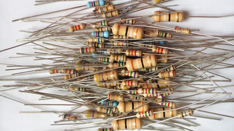
Resistor values are measured in Ohms, which indicates electrical resistance. A brand new, still-in-the-packaging resistor should have its Ohms value printed out for easy reading, but any resistors that have been unboxed (or, say, found in a toolbox or drawer) won't offer that luxury. This is where those colored bands on a resistor's body come into play.
What the colors mean
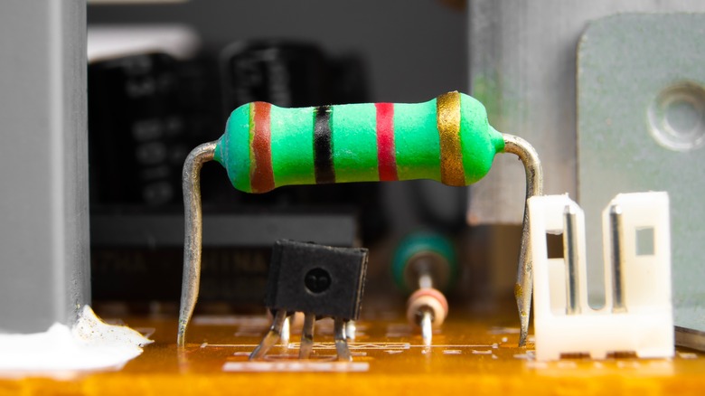
As explained by Arduino to Go, each color band on the resistor corresponds to a number but this can differ depending on the band's placement. It's not complicated, but the sheer number of colors and how their placement can affect a resistor's Ohm value makes trying to memorize everything somewhat challenging. In essence (again, depending on placement):
- Brown is one, or a multiplier of 10.
- Red is two, or a multiplier of 100.
- Orange is three, or a 1,000 multiplier.
- Yellow is four, or a multiplier of 10,000.
- Green is five, or a multiplier of 100,000.
- Blue is six, or a 1,000,000 multiplier.
- Purple is seven, but has no multiplier.
- Grey is eight, also with no multiplier.
- White is nine, no multiplier.
- Black is a zero, or a multiplier of one.
Silver and gold are the two exceptions to this pattern in that they don't represent a number or multiplier. Instead, they indicate a 10- to 5-percent (respectively) range in accuracy — meaning a gold band resistor could have a 5-percent higher or lower Ohms value due to possible variance in the manufacturing process.
Reading the bands
Parsing various resistor band colors is fairly simple once you know what each color means.
- Orient the resistor with the gold or silver band on the far right.
- Note the color on the far left — this is the first digit.
- The second color from the left is the second digit.
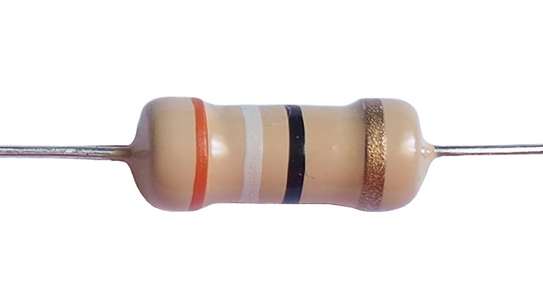
- It's important to remember these values are not added together but act as the first and second digits in a single number. So if the far-left band is orange (3) and the next band in is white (9), that comes to 39.
- The third band in is the multiplier, so ignore the color's digit value and note the multiplier value instead.
- So if the third band from the left is black (orange, white, black), the multiplier would be 1. Multiply 39 by 1 and you get the base Ohm value of the resistor: 39.
- The final band is always silver or gold. This shows how much variance there might be to the resistor's Ohm value.
- If our example resistor ended in gold (orange, white, black, gold), its 39 Ohms value could be five percent higher or lower. For a possible minimum of 37.05 or a maximum of 40.95.
These color bands and the necessary orientation to read them are universal, no matter the resistor brand. In the event you come across a five-band resistor, it reads the same except as a three-digit (i.e. the first three bands) number with multiplier (fourth band) and percent variable (fifth band).